

A parachute can determine the outcome of a space mission in a matter of seconds. For more than half a century, these systems have helped return spacecraft crews safely to Earth. However, how can an apparently ordinary piece of fabric withstand such substantial forces? Why do engineers deliberately incorporate holes and slits into parachute canopies? And how can engineers predict the behavior of a parachute as it deploys in turbulent flow at supersonic speeds?
To identify the answers, let us examine the complete development process of the space parachute, from the initial aerodynamic calculations through testing, during which engineers deliberately induce component failures.
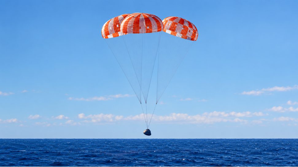
Why is it so challenging to decelerate a spacecraft?
When a spacecraft returns to Earth, it enters the atmosphere at an exceptionally high speed. At this stage, a conventional parachute would be ineffective, as the aerodynamic forces could exceed the capacity of its fabric and suspension lines.
Therefore, the spacecraft loses most of its velocity as a result of atmospheric drag, and the parachute system is deployed only during the final stage of descent. Its purpose is to reduce the remaining velocity to a level at which the capsule can land or splash down safely. Although it may appear that simply increasing the canopy area would sufficiently slow the spacecraft’s descent, doing so presents a fundamental engineering challenge: the greater the aerodynamic drag generated by the parachute, the greater the structural loads it must withstand. This challenge is further compounded by the fact that drag depends not only on canopy area but also on air density and the square of the spacecraft’s speed. Consequently, a parachute that performs effectively under certain atmospheric conditions may be unsuitable under others.
This challenge is particularly pronounced on Mars. Near the planet’s surface, its atmosphere is approximately 100 times less dense than Earth’s. To generate sufficient deceleration, the parachute must be deployed substantially earlier, while the spacecraft is still traveling at supersonic speeds.
That is precisely how the Perseverance rover landed. Its 21.5-meter (70.5-foot) diameter parachute deployed at a speed of approximately 1,510 km/h (938 mph). Unlike crewed capsules on Earth, which may use several main parachutes, the rover used a single supersonic canopy.
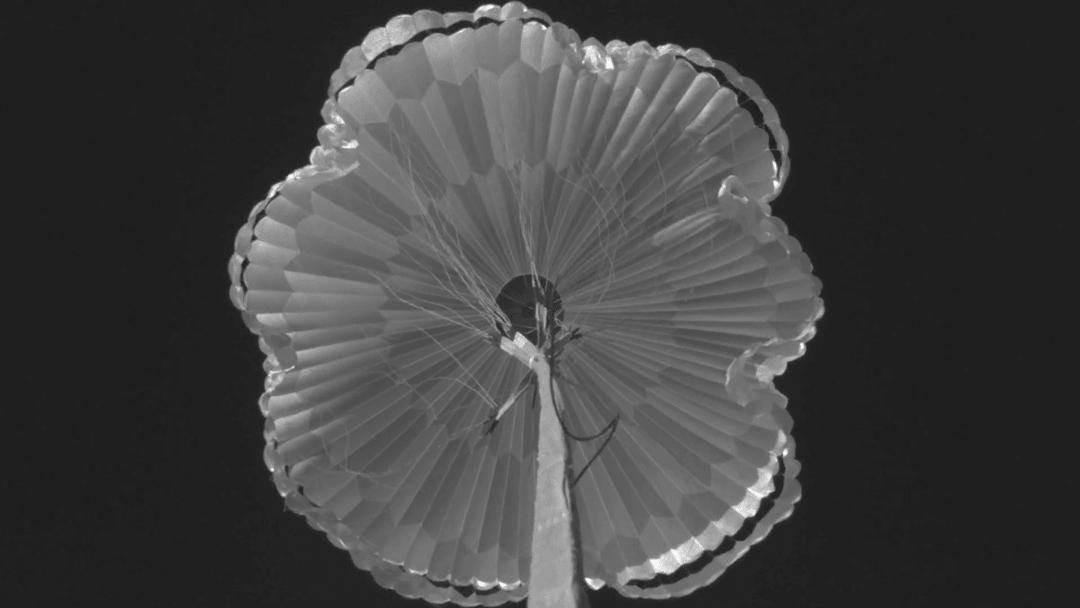
Image: NASA/JPL-Caltech
The engineers therefore needed to develop a design that would provide substantial aerodynamic drag, remain lightweight, and withstand extremely rapid deployment. The first step in addressing this challenge is determining the shape of the dome itself.
Why are parachutes used in space exploration intentionally designed with holes?
At first glance, the ideal parachute might appear to be a solid fabric hemisphere designed to trap as much air as possible. In practice, however, this configuration does not always produce optimal results. A region of high pressure forms beneath the canopy, while complex vortex flows develop around it. These phenomena can cause oscillations, uneven inflation, and substantial localized stresses on the fabric.
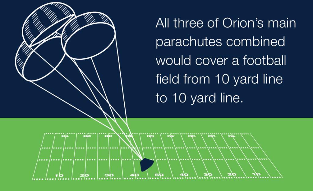
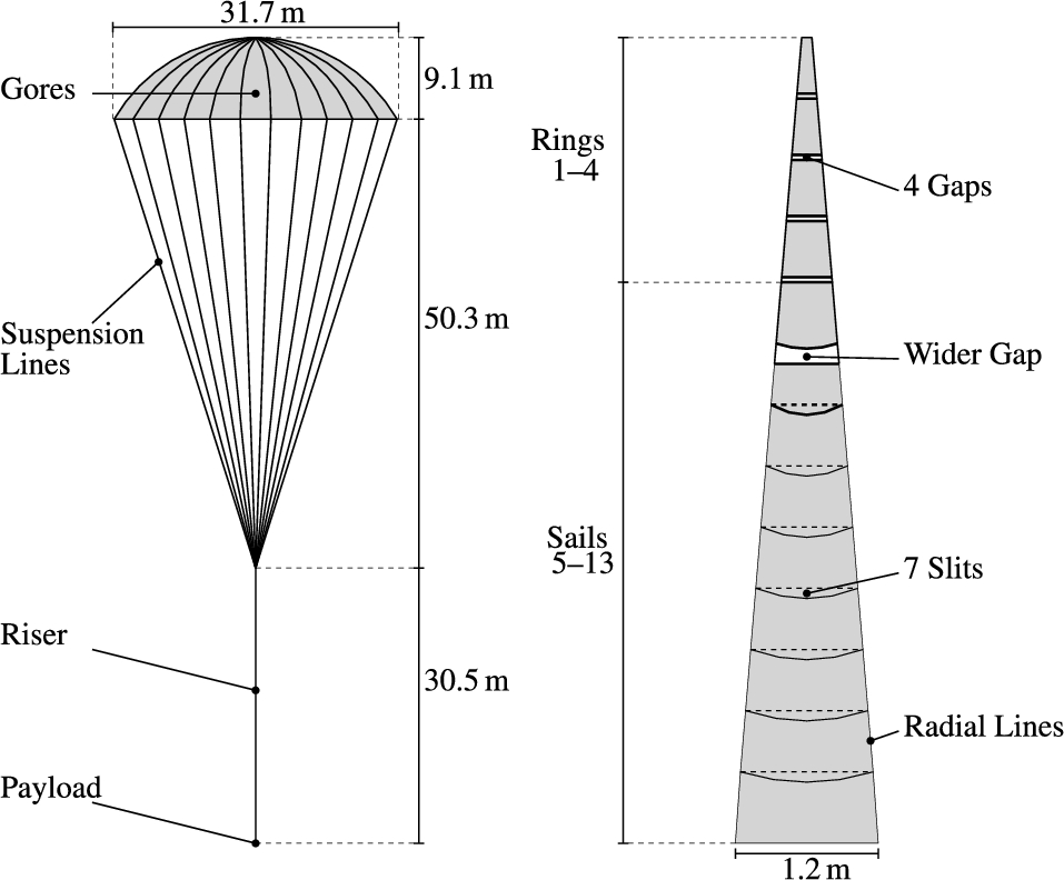
For this reason, engineers seek not only to maximize drag but also to ensure that the canopy behaves predictably. One approach is to allow some airflow through specially designed openings and slits. The Orion spacecraft’s main parachutes were designed according to this principle. They feature a ringsail configuration, in which the fabric is divided into distinct rings and sail-like sections. The gaps between these sections help regulate pressure distribution and stabilize the canopy during descent.
However, selecting the appropriate geometry is only one aspect of the challenge. A space parachute must be exceptionally strong while remaining as lightweight as possible. Nylon is primarily used in the manufacture of Orion’s main canopies, while high-strength Kevlar fibers are incorporated into load-bearing components. Each main parachute weighs approximately 122 kg (270 pounds), despite having a diameter of 35.4 m (116 feet).
An even more striking example is the ExoMars parachute system. Its largest canopy, measuring 35 m (115 feet) in diameter, weighs only 74 kg (163 pounds). At the same time, the fabric area exceeds 800 m² (8,600 sq. ft.), and its areal density is approximately 40 g/m² (1.18 oz/sq. yd.). A straightforward calculation indicates that the fabric itself weighs approximately 32 kg (71 lb). The remainder of the mass comprises reinforcements, seams, slings, and other structural elements. In other words, a significant portion of the parachute’s mass does not contribute to generating aerodynamic drag; rather, it enables that force to be transferred to the spacecraft without compromising the structure.
This is where another equally important component of the parachute system comes into play: the risers.
How can such slender slings support a capsule weighing several metric tons?
The suspension lines serve purposes beyond connecting the canopy to the spacecraft. They transmit aerodynamic forces, help maintain the canopy’s geometry, and determine its behavior under load. For example, each of Orion’s three main parachutes has 80 slings, each rated to withstand a force of at least 6.7 kN (1,500 pound-force). The combined length of the main canopy slings is approximately 16 km (10 miles).
However, it would be inaccurate to assume that the load is distributed evenly among all the slings. During deployment, the canopy may inflate asymmetrically, causing some straps to become more tightly tensioned than others and resulting in uneven deformation of the fabric. The calculated maximum load on a single Orion main parachute is approximately 205 kN (46,000 pound-force).
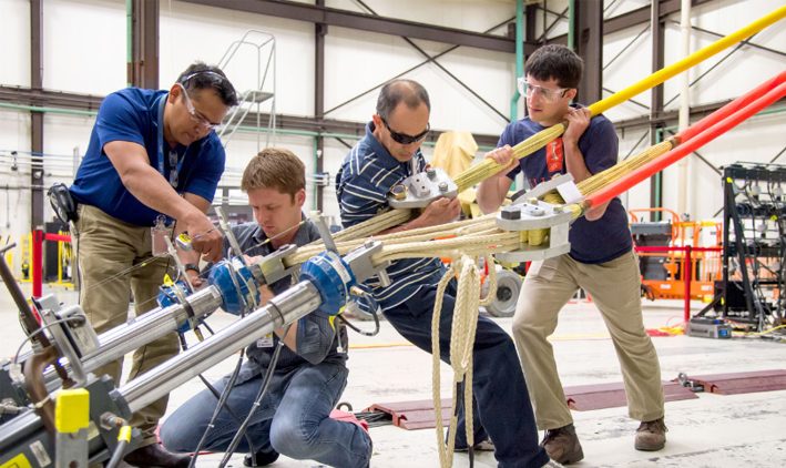
Therefore, selecting the appropriate material strength alone is insufficient. Engineers must ensure that the canopy, risers, and suspension system function as an integrated structure. However, even a meticulously designed parachute may fail if its most hazardous operational phase — deployment — is not properly managed.
The most critical moments: How to deploy a parachute correctly
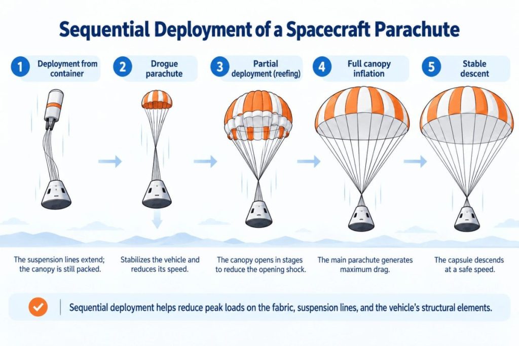
Paradoxically, the greatest risk to a parachute may arise not during a prolonged descent under load, but in the first moments after it exits its container. When folded, the canopy occupies a relatively small volume. Upon entering the airflow, the fabric begins to inflate rapidly, causing the aerodynamic load to increase sharply. If a large canopy is allowed to deploy instantaneously at high speed, the resulting load impulse may damage the fabric, suspension lines, or even the spacecraft’s structural components.
For this reason, modern parachute systems typically employ a multi-stage deceleration process. First, small deceleration parachutes deploy to stabilize the capsule and reduce its speed. The main parachutes are deployed only afterward. For example, Crew Dragon uses two drogue parachutes and four main parachutes. The drogue parachutes deploy at an altitude of approximately 5.5 km (18,000 feet), when the capsule is traveling at about 563 km/h (350 mph). The main parachutes begin to deploy at a lower altitude — approximately 1.8 km (6,000 feet) — once the speed has decreased to 193 km/h (120 mph).
In addition, reefing technology is employed to temporarily restrict the dome’s deployment. Specialized tensioning elements initially prevent the dome from fully inflating. Once the speed has decreased, the dome proceeds to the next deployment stage. Consequently, rather than producing a single, sharp braking impulse, the system generates several sequential loading stages.
However, the options for this type of deceleration on Mars are limited. Because of the planet’s thin atmosphere, the supersonic parachute must deploy extremely rapidly. During Earth-based tests conducted as part of the ASPIRE program, the parachute designed for Perseverance deployed in just 0.4 seconds and withstood a peak load of approximately 298 kN (67,000 pound-force). The tests were conducted at Mach 1.8, and the measured load was approximately 85% greater than the load expected during the rover’s actual landing.
The ExoMars mission also demonstrated the considerable challenges involved in ensuring safe deployment. During high-altitude tests in 2019, both main parachutes sustained critical damage. The cause was not attributed solely to the strength of the canopies. Engineers reviewed the design of the containers from which the parachutes were deployed, as well as the sequence in which the lines and fabric were released. Following these changes, ground tests were completed successfully without any tears, even at a deployment speed of approximately 200 km/h (124 mph). Further testing also led to additional reinforcement of certain components.
This example demonstrates that a parachute’s reliability is determined not only by the strength of its canopy but also by the ability to anticipate precisely how it will deploy from its container, inflate, and change shape during the initial seconds. How, then, can these processes be studied when each real-world test requires extensive preparation, specialized equipment, and substantial expenditure?
This is where the most compelling aspect of modern design begins: mathematical modeling.
How engineers calculate the parachute: Orion’s virtual drop
For a rigid aircraft wing, its geometry can be modeled, and the airflow around it calculated. The situation is considerably more complex for a parachute, whose shape is not constant. Under the influence of airflow, the fabric expands, contracts, oscillates, and changes curvature. Each of these deformations, in turn, affects the characteristics of the airflow.
An interdependent process occurs: the air alters the shape of the dome, while the dome alters the movement of the air.
In mathematical modeling, this phenomenon is known as fluid–structure interaction (FSI), which refers to the interaction between a fluid or gas and a deformable structure. To simulate this process, engineers develop a numerical model that simultaneously describes the motion of the air, the deformation of the fabric, and the stresses in the slings.
However, this presents another challenge: the geometry is exceptionally complex. An early version of the Orion main parachute used in the calculations comprised 80 sectors and approximately 760 gaps and openings. Accurately simulating airflow through each feature would require an exceptionally detailed computational grid. Even on a powerful supercomputer, such a calculation could demand substantial computational resources.
Therefore, the researchers developed a specialized approach — HMGP (Homogenized Modeling of Geometric Porosity). This approach represents the hundreds of small slits used in airflow calculations in terms of an equivalent local permeability, while preserving the geometry of the dome in the structural model. When combined with FSI methods, it enables the development of three-dimensional numerical models that account for the complex interaction between airflow and the flexible fabric. However, the primary benefit of these calculations lies not in the level of detail achieved in the computer simulation, but in the ability to evaluate design solutions before manufacturing a prototype parachute.
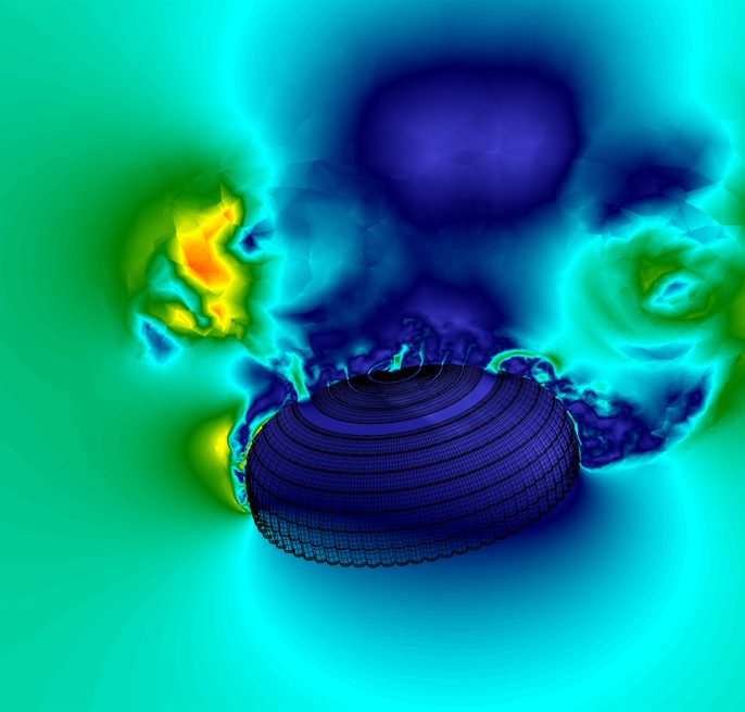
For example, engineers examined how aerodynamics vary with sling length. Across six design configurations, the ratio of sling length to dome diameter ranged from 1.00 to 1.76. Within this range, the projected canopy area increased by approximately 13.5%, while the drag coefficient increased by 27%. Therefore, even without changing the material or adding fabric, parachute performance can be significantly influenced by carefully selecting the geometry of the suspension system. This is just one example.
Modern models enable researchers to examine not only individual canopies but also the interactions among multiple parachutes operating in close proximity. This capability is particularly important for Orion, as its three main canopies do not function as independent systems. Each canopy is exposed to turbulent airflow generated by the neighboring parachutes. Computer simulations help assess these interactions, identify hazardous conditions, and select configurations for further physical testing.
As a result, the approach to designing space parachutes is evolving. During the Apollo program, more than one hundred tests were conducted to verify parachute systems. By comparison, NASA estimates that approximately 20–25 tests were sufficient for Orion, owing to accumulated experience and modern analytical methods. This does not mean that computer simulations have completely replaced real-world experiments. Rather, they have helped engineers better determine which operating conditions require physical testing. Even the most detailed mathematical model cannot guarantee that a parachute will function flawlessly under real-world conditions.
What occurs if the parachute fails?
In space technology, the risk of failure cannot be eliminated entirely. The fabric may tear, the straps may become tangled, and the deployment mechanism may malfunction. Accordingly, after completing calculations and conducting strength tests, engineers must address an additional challenge: ensuring mission safety in the event of a partial system failure.
The most straightforward solution is to establish a reserve.
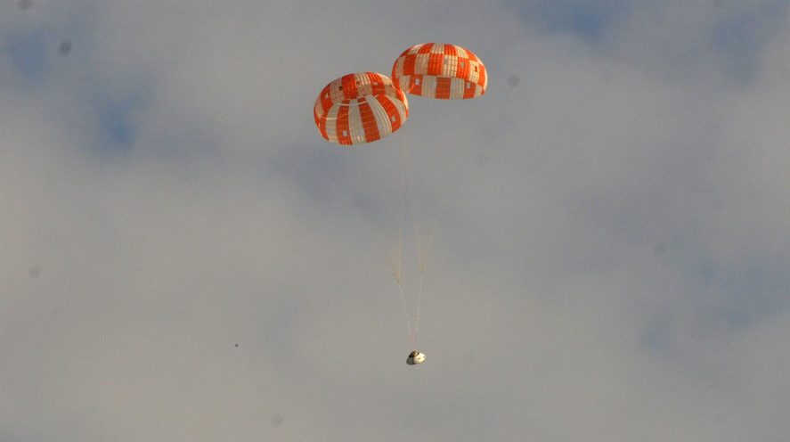
The Apollo program had already demonstrated its effectiveness. The command module employed three main parachutes but was designed to ensure a safe splashdown even if only two deployed. In 1971, this capability was tested during the return of Apollo 15. At an altitude of approximately 1,800 meters (5,900 feet), one of the three main parachutes failed, likely as a result of damage caused by fuel jettisoned from the capsule. The splashdown speed increased from 31 to 35 km/h (19–22 mph), but the crew remained unharmed.
The modern Orion has continued to uphold this principle. Its system is designed to ensure a safe descent even if one of the main parachutes and one of the two brake parachutes fail. NASA specifically simulated these scenarios during testing.
However, reservations may not always be possible.
On Mars, adding a second supersonic parachute would increase mass, require new mechanisms, and introduce the risk of components becoming entangled during deployment. Accordingly, for Perseverance, the team chose to provide the main canopy with a substantial strength margin and to implement an exceptionally rigorous testing program.
Another type of danger arises when the parachute itself remains functional, but the command to deploy it is never received. This is precisely what happened to the Genesis spacecraft in 2004. Because the G-sensors were incorrectly oriented, the parachute system failed to activate, and the capsule containing samples of solar wind crashed into the desert at approximately 311 km/h (“193 mph”). Some scientific data were recovered, but many collectors were shattered, and the samples were contaminated by soil and debris from the heat shield.
This accident demonstrated that constructing a robust canopy and reliable suspension lines alone is insufficient. Landing safety depends on the entire system, including the sensors, electronics, deployment mechanisms, and the proper sequence of their operation. This is particularly critical for missions involving the return of space samples, where preserving the capsule’s integrity is not enough; its contents must also be protected from terrestrial contamination.
Why cannot a parachute designed for space applications be installed on an airliner?
In light of the foregoing, a logical question arises: if parachutes can safely lower space capsules weighing several metric tons, why are they not used to rescue passenger airliners?
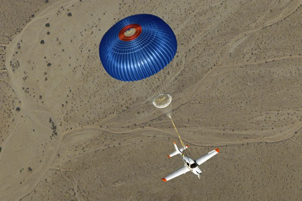
Source: Smithsonian Magazine
Parachute rescue systems are already used in aviation. For example, BRS/CAPS systems enable an entire light aircraft, including its occupants, to descend safely to the ground. However, their purpose differs somewhat from that of space parachutes. An aviation rescue system typically employs a large, round canopy deployed by a specialized rocket. Its suspension lines are attached to the aircraft’s structural components, and the system must be designed to withstand the sudden shock of deployment.
Once the canopy has been deployed, the aircraft loses a substantial portion of its horizontal speed and transitions to a nearly vertical descent. At this stage, the pilot has virtually no control over the landing location, which depends largely on wind conditions. For example, the CAPS system used on Cirrus aircraft provides a descent rate of approximately 9 m/s (30 ft/s). Accordingly, saving lives depends not only on the parachute but also on the design of the fuselage and seats, which help absorb impact energy. However, as the aircraft’s mass increases, the challenge quickly becomes more complex.
Let us consider a simplified example. For a 70-metric-ton (154,000-pound) airliner to descend vertically near sea level at approximately 7 m/s (23 feet per second), even with an optimistic drag coefficient of 1.5, a parachute with an effective area of approximately 15,000 m² (161,000 square feet) would be required. This is equivalent to a circular canopy approximately 140 m (459 ft) in diameter, with an area exceeding that of two standard soccer fields.
This represents only a simplified estimate of the required aerodynamic area. A practical system would require a substantial quantity of fabric, load-bearing straps, deployment mechanisms, and additional structural reinforcement for the aircraft. Further challenges include the aircraft’s high cruising speed, the limited altitude available in many emergency situations, and the difficulty of ensuring a safe landing following a vertical descent.
Therefore, the issue is not the fundamental impossibility of using a parachute on a large aircraft, but rather the exceptionally complex engineering trade-offs involving weight, size, strength, and efficiency.
Sport parachutes serve an entirely different purpose.
A modern sports parachute typically has the shape of a rectangular wing with air-filled chambers, a configuration known as a ram-air design. In addition to creating drag, it generates lift, enabling the skydiver to glide, change direction, and reduce vertical speed before landing. Maneuverability is one of the primary priorities for this type of parachute.
In contrast, ringsail and disk-gap-band space structures are primarily designed to provide stable deceleration. Although active maneuvering is not necessarily required, these structures must operate across a broad range of speeds, withstand high loads, and reliably deploy after prolonged storage.
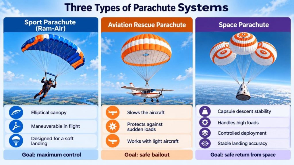
However, the distinction between these approaches is gradually becoming less clear.
For example, NASA’s X-38 experimental spacecraft was designed to use a large, steerable parafoil — a wing-shaped parachute that not only slows its descent but also enables adjustments to its flight path and landing site.
The LOFTID project demonstrated another promising approach. Rather than enlarging the conventional fabric dome, engineers employed an inflatable aerodynamic heat shield to decelerate the spacecraft during high-speed reentry. Conventional parachutes remain responsible for the final deceleration.
Such technologies may be particularly significant for future heavy-lift missions to Mars, where the thin atmosphere imposes limitations on conventional parachute systems.
Technology that allows no margin for error
At first glance, a space parachute may appear to be one of the simplest systems aboard a spacecraft. However, its design relies on complex calculations involving aerodynamics, the mechanics of flexible membranes, material strength, and the interaction between airflow and the fabric.
It is insufficient for engineers merely to construct a robust dome. They must anticipate how it will be filled, where the greatest loads will occur, how the trusses will behave, and what may happen if individual components fail.
This is precisely why even the most advanced supercomputer models do not replace real-world testing; rather, they enable it to be conducted in a more targeted manner.
Ultimately, all these calculations, years of development, and dozens of experiments serve one purpose: to ensure that, following a long spaceflight, the parachute deploys at precisely the right moment and brings the mission to a safe conclusion.
